
< Previous | Contents | Next >
Section 4 Scantlings of Structural Members
401. General
1. For the primary structural members which contribute to the overall strength, the scantlings are to
be determined in accordance with the requirements in Sec 2 and
402. and 403. may be applied.
2. For the structural members subjected to local loads only, the
Classification of Steel Ships may be applied under the approval
3. However, the requirements in
requirements in Rules for the
of the Society.
402. Thickness of plating of hull structure
The thickness of plating of the primary hull structure such as shell plating which contributes to the overall strength, subjected to distributed loads, is not to be less than obtained from the following formulae, whichever is the greater.
Ρ̓
Üᾜᾯ
KJǾĪĊ ÜÅᾙ
ÑǼ ĴLǾKĊΡ̓
Üᾜᾏ Nmm Ń ,
ÜÅᾬ
Ñ Ǽ Nmm Ń
Ċ :
ᾜᾯ :
ᾜᾏ :
Åᾙ :
Spacing of transverse or longitudinal frames(m ). Head of water in static loading specified in 301.(m ).
Head of water in combined loading specified in 301.(m ).
As given by the following formulae, whichever is the smaller.
ĪĮJŇᾟſſᾯÌ Ø Üᾟ
ĪĮJ
ÌǾĨJN Üᾟ ŇᾟſſᾯĪ Ń
Åᾬ : As given in (a) or (b) below.
(a) Where ſſᾏÌ × ſſᾏĪ Q L, the value given by the following formulae, whichever is the smaller.
ᾏÌ
JKJL Ň ᾟĪſſĪ ÜĪĮJᾟ Ø
N
ĪĮJ Ň ᾟÔſſᾏĪ
Ī Üᾟ Ô Ń
(b) Where ſſᾏÌ × ſſᾏĪ P L, the value given by the following formulae, whichever is the smaller.
JKJL Ň ᾟĪſſĪ
ĪĮJ Ň ᾟÔſſ ÔŇ ᾟÔſſ Ô
Ü ᾏÌ Ø
ĪN Ü ŃᾏÌ ᾏĪ
ĪĮJᾟ ᾟ
ſſᾯÌ,
ſſᾯĪ
and ſſᾏÌ,
ſſᾏĪ
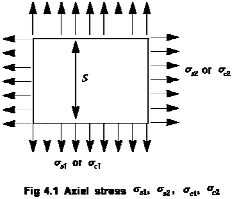
: Axial stresses acting on the plating in static loading and com-
bined loading, respectively (NÕmmĪ). (See Fig 4.1)
ᾟ : Material factor, as given in the following.
Mild steels 1.00
High tensile steels
A 32, DH 32, EH 32 0.78
AH 36, DH 36, EH 36 0.72
For other high tensile steels, the value of k is to be dedicated at the discretion of the Society.
![]()
Ǽ : Corrosion allowance specified in 211.
Ch 4 Design Condition Ch 4
![]()

403. Section modulus of transverse or longitudinal frames
The section modulus of transverse or longitudinal frames which support the panels prescribed in
402. is to be obtained from the following formula.
N
Ī
ÌLKĶǼ ÜĪĮJŇᾟſſ Ń
Ncm Ń
ᾟĊᾜᾏ ᾨ
Į
ᾏL
Ǽ : Coefficient given below.
1.0 for both ends fixed
1.5 for both ends simply supported
ᾨ ſſᾏL
: Span of frames (m ).
: Axial stress in combined loading (NÕmm Ī).
Ċ, ᾜᾏ, ᾟ : As specified in 402.
404. Local buckling of cylindrical shells
Unstiffened or ring-stiffened cylindrical shells subjected to axial compression or compression due to bending, and having proportions which satisfy the following relationship are to be checked for local buckling in addition to the overall buckling as specified in 303.
ÁÕᾼ Q ĂÕĶ ſſ←
Á : Diameter of cylindrical shell
ᾼ : Thickness of shell plating
(Á and ᾼ expressed in the same units.)
ſſ← : Specified minimum yield stress of the material
¢ : Modulus of elasticity of the material
(ſſ← and ¢ expressed in the same unit system.)
Ch 4 Design Condition Ch 4
![]()